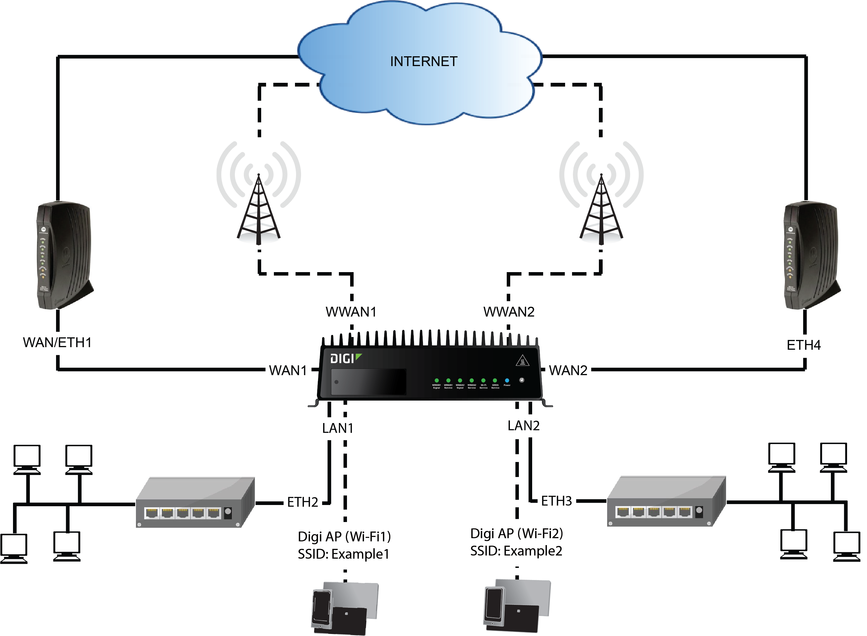
The default configuration of the TX54 consists of one WAN (WAN1),
- WAN1: WAN/ETH1 Ethernet port
-
- WWAN2: WWAN2 cellular modem
LAN1 is configured to use the LAN1 bridge. Its default IP address is 192.168.2.1, and it has its DHCP server enabled. . The default configuration of the LAN1 bridge consists of the following devices:
- ETH2
- ETH3
- ETH4
-
- WWAN2 cellular modem
In this example, we will
Note To avoid potential problems with access to the device while performing these procedures, you should use the serial port to perform these tasks, or, if you are using an Ethernet connection, it should be connected to LAN1 through the ETH2 Ethernet port.
Task one: Configure bridges
In this task, we will create a new bridge and configure the LAN1 and LAN2 bridges to use the following devices:
- LAN1 bridge:
- ETH2
- LAN2 bridge:
- ETH3
- Digi AP (Wi-Fi2)
![]()
In task two, we will assign the new LAN2 bridge to a LAN.
Note The example command and output in this procedure are based on a dual-Wifi configuration. Commands and output will vary slightly if your TX54 device is a single-WiFi model.
- Select the device in Remote Manager and click Actions > Open Console, or log into the TX54 local command line as a user with full Admin access rights.
Depending on your device configuration, you may be presented with an Access selection menu. Type admin to access the Admin CLI.
- At the command line, type config to enter configuration mode:
> config
(config)>
- Display a list of devices currently configured for the LAN1 bridge:
- Method one: Enter the full command at the config prompt:
(config)> show network bridge lan1 device
0 /network/device/eth2
1 /network/device/eth3
2 /network/device/eth4
3 /network/wireless/ap/digi_ap1
4 /network/wireless/ap/digi_ap2
(config)>
- Method two: Move within the configuration to the network bridge lan1 device location and the use the show command display the list of devices:
- Change to the network node:
(config)> network
(config network)>
- Change to the bridge node:
(config network)> bridge
(config network bridge)>
- Change to the lan1 node:
(config network bridge)> lan1
(config network bridge lan1)>
- Change to the device node:
(config network bridge lan1)> device
(config network bridge lan1 device)>
- Enter show:
(config network bridge lan1 device)> show
0 /network/device/eth2
1 /network/device/eth3
2 /network/device/eth4
3 /network/wireless/ap/digi_ap1
4 /network/wireless/ap/digi_ap2
(config network bridge lan1 device)>
- Change to the network node:
Note For the rest of this example configuration, command line examples will use a single command entered at the root config prompt (method one above). However, any command line example in this example configuration can also be performed by moving within the configuration to the appropriate location (method two above).
- Method one: Enter the full command at the config prompt:
- Remove devices from the LAN1 bridge that will be used by other interfaces in this configuration.
(config)> del network bridge lan1 device 4
(config)>
- Remove the ETH4 device (/network/device/eth4) from the bridge, using its index number, 2, as determined above with the show command:
(config)> del network bridge lan1 device 2
(config)>
- Remove the ETH3 device (/network/device/eth3) from the bridge, using its index number, 1, as determined above with the show command:
(config)> del network bridge lan1 device 1
(config)>
- Use the show command again to verify that the LAN1 bridge now has only two devices, ETH2 and Digi AP (Wi-Fi1):
(config)> show network bridge lan1 device
0 /network/device/eth2
1 /network/wireless/ap/digi_ap1
(config)>
- Create a new bridge, named LAN2:
(config)> add network bridge LAN2
(config network bridge LAN2)>
- Add devices to the bridge:
- View available devices and the proper syntax by using the add device command with the TAB autocomplete feature:
(config network bridge LAN2)> add device end <TAB>
(config network bridge LAN2)> add device end /network/<TAB>
/network/device/eth1          /network/device/eth2          /network/device/eth3
/network/device/eth4          /network/device/loopback      /network/bridge/LAN2
/network/bridge/lan1          /network/wireless/ap/digi_ap1 /network/wireless/ap/digi_ap2
(config network bridge LAN2)>
- Add the ETH3 device to the bridge:
(config network bridge LAN2)> add device end /network/device/eth3
(config network bridge LAN2)>
(config network bridge LAN2)> add device end /network/wireless/ap/digi_ap2
(config network bridge LAN2)>
- Use the show command again to verify that the LAN2 bridge now has two devices, ETH3 and Digi AP (Wi-Fi2):
(config network bridge LAN2)> show network bridge lan2 device
0 /network/device/eth3
1 /network/wireless/ap/digi_ap2
(config network bridge LAN2)>
- View available devices and the proper syntax by using the add device command with the TAB autocomplete feature:
- Save the configuration and apply the change
(config network bridge LAN2)> save Configuration saved. > - Type exit to exit the Admin CLI.
Depending on your device configuration, you may be presented with an Access selection menu. Type quit to disconnect from the device.
Task two: Create a new LAN
In this task, we will create a new LAN, named LAN2, to use the LAN2 bridge created in task one.
Note The example command and output in this procedure are based on a dual-Wifi configuration. Commands and output will vary slightly if your TX54 device is a single-WiFi model.
- Select the device in Remote Manager and click Actions > Open Console, or log into the TX54 local command line as a user with full Admin access rights.
Depending on your device configuration, you may be presented with an Access selection menu. Type admin to access the Admin CLI.
- At the command line, type config to enter configuration mode:
> config
(config)>
- Add a new network interface named LAN2:
(config)> add network interface LAN2
(config network interface LAN2)>
- Configure the device for the LAN2 interface:
- Enter device ? to view available devices and the proper syntax.
(config network interface LAN2)> device ?

Device: The network device used by this network interface.
Format:
  /network/device/eth1
  /network/device/eth2
  /network/device/eth3
  /network/device/eth4
  /network/device/loopback
  /network/bridge/LAN2
  /network/bridge/lan1
  /network/wireless/ap/digi_ap1
  /network/wireless/ap/digi_ap2
Current value:

(config network interface LAN2)> device
- Set the device for the LAN2 interface to the LAN2 bridge created in task one:
(config network interface LAN2)> device /network/bridge/LAN2
(config network interface LAN2)>
- Enter device ? to view available devices and the proper syntax.
- Configure the firewall zone for the LAN2 interface to internal:
(config network interface LAN2)> zone internal
(config network interface LAN2)>
- Configure the IPv4 address for the LAN2 interface:
(config network interface LAN2)> ipv4 address 192.168.3.1/24
(config network interface LAN2)>
- Enable the DHCP server for the LAN2 interface:
(config network interface LAN2)> ipv4 dhcp_server enable true
(config network interface LAN2)>
- Enable the access points and set the SSIDs:
- Move to the root of the configuration schema by typing three periods (...):
(config network interface LAN2)> ...
(config)>
- Enable the Digi AP (Wi-Fi1) access point:
(config)> network wifi ap digi_ap1 enable true
(config)>
- Set the SSID for the Digi AP (Wi-Fi1) access point:
(config)> network wifi ap digi_ap1 ssid Example1
(config)>
- Set the password for the Digi AP (Wi-Fi1) access point:
(config)> network wifi ap digi_ap1 encryption key_psk2 password1
(config)>
- Enable the Digi AP (Wi-Fi2) access point:
(config)> network wifi ap digi_ap2 enable true
(config)>
- Set the SSID for the Digi AP (Wi-Fi2) access point:
(config)> network wifi ap digi_ap1 ssid Example2
(config)>
- Set the password for the Digi AP (Wi-Fi2) access point:
(config)> network wifi ap digi_ap2 encryption key_psk2 password2
(config)>
- Move to the root of the configuration schema by typing three periods (...):
- Save the configuration and apply the change
(config network bridge LAN2)> save Configuration saved. > - Type exit to exit the Admin CLI.
Depending on your device configuration, you may be presented with an Access selection menu. Type quit to disconnect from the device.
Task three: Create a new WAN
In this task, we will create a second WAN interface, named WAN2, using the ETH4 device.
- Select the device in Remote Manager and click Actions > Open Console, or log into the TX54 local command line as a user with full Admin access rights.
Depending on your device configuration, you may be presented with an Access selection menu. Type admin to access the Admin CLI.
- At the command line, type config to enter configuration mode:
> config
(config)>
- Add the WAN2 network interface:
(config)> add network interface WAN2
(config network interface WAN2)>
- Enter device ? to view available devices and the proper syntax.
(config network interface WAN2)> device ?

Device: The network device used by this network interface.
Format:
  /network/device/eth1
  /network/device/eth2
  /network/device/eth3
  /network/device/eth4
  /network/device/loopback
  /network/bridge/LAN2
  /network/bridge/lan1
  /network/wireless/ap/digi_ap1
  /network/wireless/ap/digi_ap2
Current value:

(config network interface WAN2)> device
- Configure the WAN to use the eth4 device:
(config network interface WAN2)> device /network/device/eth4
(config network interface WAN2)>
- Change the zone for the WAN to external:
(config network interface WAN2)> zone external
(config network interface WAN2)>
- Configure the WAN as an IPv4 DHCP client:
- Enter ipv4 ? to determine the available settings for ipv4 (the appropriate setting is highlighted in the example output):
(config network interface WAN2)> ipv4 ? IPv4 Parameters Current Value ------------------------------------------------------------------------------- address Address enable true Enable gateway Default gateway metric 0 Metric mgmt 0 Management priority mtu 1500 MTU type static Type weight 10 Weight Additional Configuration ------------------------------------------------------------------------------- connection_monitor Active recovery dhcp_relay DHCP relay dhcp_server DHCP server dns DNS servers (config network interface WAN2)> ipv4 - Enter ipv4 type ? to determine available settings for the ipv4 type:
(config network interface WAN2)> ipv4 type ? Type: The method for configuring IPv4 on this interface. Format: dhcp static Default value: static Current value: static (config network interface WAN2)> ipv4 type - Set the IPv4 type to dhcp:
(config network interface WAN2)> ipv4 type dhcp
(config network interface WAN2)>
- Enter ipv4 ? to determine the available settings for ipv4 (the appropriate setting is highlighted in the example output):
- Configure the IPv4 WAN priority.
Because the TX54 device now has two WANs, we need to determine which WAN will be the default route when both WANs are active. In this example configuration, WAN1 should be the primary WAN, and WAN2 only used when WAN1 is down. Additionally, the Wireless WANs will provide additional failover capabilities and will be used only when both WAN1 and WAN2 are unable to connect to the internet.
To do this, we will set the metric for WAN2 to a value that is higher than the metric for WAN1, and lower than the metric for the WWANs.
- Determine the metric for WAN1:
(config network interface WAN2)> show .. wan1 ipv4 metric 1 (config network interface WAN2)> - Determine the metric for
config network interface WAN2)> show .. wwan1 ipv4 metric 3 (config network interface WAN2)> - Determine the metric for WWAN2
config network interface WAN2)> show .. wwan2 ipv4 metric 3 (config network interface WAN2)> - Set the metric for WAN2 to 2, which is higher than the WAN1 metric and lower than the WWAN metrics:
(config network interface WAN2)> ipv4 metric 2
(config network interface WAN2)>
- Determine the metric for WAN1:
- Save the configuration and apply the change
(config network bridge bridge2)> save Configuration saved. > - Type exit to exit the Admin CLI.
Depending on your device configuration, you may be presented with an Access selection menu. Type quit to disconnect from the device.
Task four: Verify the new configuration
The final step in this example is to verify the new configuration.
- Connect an Ethernet cable from an internet-connected modem to WAN1 through the WAN/ETH1 Ethernet port.
- Verify that
- Connect a device to LAN1 through the ETH2 Ethernet port, or by connecting to the
- Verify that the device has been provided an IP address from the LAN1 DHCP server in the 192.168.2.* subnet.
- Verify that the device has access to the internet.
- Connect a device to LAN1 through the ETH2 Ethernet port, or by connecting to the
- Verify that LAN2 is operating correctly:
- Connect a device to LAN2 through the ETH3 Ethernet port, or by connecting to the Digi AP (Wi-Fi2) access point
- Verify that the device has been provided an IP address from the LAN2 DHCP server in the 192.168.3.* subnet.
- Verify that the device has access to the internet.
- Connect a device to LAN2 through the ETH3 Ethernet port, or by connecting to the Digi AP (Wi-Fi2) access point
- Verify that WAN priority and failover are operating correctly between WAN1 and WAN2:
- Connect an Ethernet cable from an alternate internet-connected modem to WAN2 through the ETH4 Ethernet port.
Verify that when both WANs are connected to the internet, devices connected to the TX54 have internet access through WAN1.
- Verify that failover functions correctly between WAN1 and WAN2:
- Disconnect the WAN1 Ethernet cable from the WAN/ETH1 Ethernet port and verify that devices connected to the TX54 have internet access through WAN2.
- Reconnect the WAN1 Ethernet cable to the WAN/ETH1 Ethernet port and verify that devices connected to the TX54 have internet access through WAN1.
- Verify that failover functions correctly if both WAN1 and WAN2 are not working:
- Insert at least one SIM in one of the cellular modems.
- When the WWAN's Service LED indicates that the device is connected to the cellular network, unplug both the WAN1 Etherent cable from the WAN/ETH1 Ethernet port, and the WAN2 Ethernet cable from the ETH4 Ethernet port.
- Verify that devices connected to the TX54 have internet access through the WWAN.
 PDF
PDF


